Probing Intangible Limits of Electrogravitic Knowledge end.
Electrogravitic Testing and Experimental Visualizations
Home Brewed Anti-Gravity Shenanigans
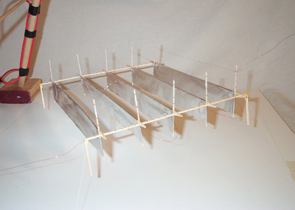
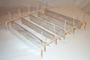
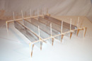
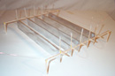
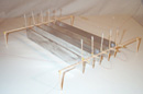
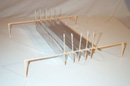
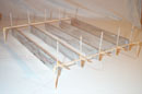
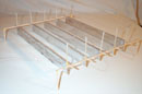
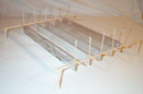
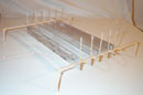
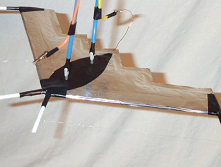
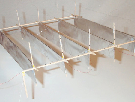
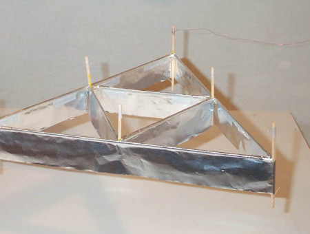
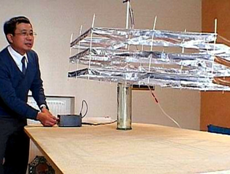
Experimental Tinker-Toy Lifter
In Pursuit of an Electrogravitic ‘Sweet Spot’
By way of explanation, provided here are a few basic details regarding this adjustable type Lifter. Weighing in at about 6 grams (sorry, my cheap hanging postal scale is none too accurate) the overall dimension is 28cm on either side, with each capacitor being 28cm long from end to end. Also, as mentioned elsewhere, currently using some rather nice 0.005” stainless steel wire purchased from MWS Wire Industries. My very simplified criteria for judging KV/mAmps used was to gradually turn up the power until strong, stable flight was achieved, then twisting power back down until the thread tethers were slightly loose, then slowly back up again until all four corners were stretched tight and stable. My only experimental regret was having no satisfactory method for measuring actual lifting force, so I only tried to be as consistent as possible in my standards for visual observation.
First Test ~ 4cm Foil Length
(average after 3 runs)
| KVs / Amps |
 Capacitors Capacitors@ 6cm |
 Capacitors Capacitors@ 5cm |
 Capacitors Capacitors@ 4cm |
 Capacitors Capacitors@ 3cm |
 Capacitors Capacitors@ 2cm |
| Wire @ 4.5cm |
27.2KV / 0.9mA |
27KV / 0.8mA |
28KV / 0.8mA |
29KV / 0.9mA |
>30KV / 0.8mA |
| Wire @ 4.0cm |
25.3KV / 0.9mA |
25.3KV / 0.8mA |
25.7KV / 0.8mA |
27KV / 0.9mA |
29.3KV / 0.9mA |
| Wire @ 3.5cm |
23.7KV / 0.9mA |
23.7KV / 0.9mA |
24KV / 0.9mA |
24.8KV / 0.9mA |
26.8KV / 1mA |
| Wire @ 3.0cm |
21.7KV / 0.9mA |
21.7KV / 0.8mA |
22KV / 1mA |
22.7KV / 1mA |
24KV / 1.1mA |
| Wire @ 2.5cm |
19.8KV / 1.3mA |
19.7KV / 1.3mA |
20KV / 1.1mA |
20KV / 1.1mA |
21.1KV / 1.4mA |
| Wire @ 2.0cm |
17.5KV / 1.5mA |
17.7KV / 1.3mA |
17.3KV / 1.4mA |
18KV / 1.4mA |
18KV / 1.4mA |
Second Test Run – 3cm Foil Length
(average after 3 runs)
| KVs / Amps |
 Capacitors Capacitors@ 6cm |
 Capacitors Capacitors@ 5cm |
 Capacitors Capacitors@ 4cm |
 Capacitors Capacitors@ 3cm |
 Capacitors Capacitors@ 2cm |
| Wire @ 4.5cm |
27.2KV / 0.9mA |
27KV / 0.8mA |
28KV / 0.8mA |
29KV / 0.9mA |
>30KV / 0.8mA |
| Wire @ 4.0cm |
25.3KV / 0.9mA |
25.3KV / 0.8mA |
25.7KV / 0.8mA |
27KV / 0.9mA |
29.3KV / 0.9mA |
| Wire @ 3.5cm |
23.7KV / 0.9mA |
23.7KV / 0.9mA |
24KV / 0.9mA |
24.8KV / 0.9mA |
26.8KV / 1mA |
| Wire @ 3.0cm |
21.7KV / 0.9mA |
21.7KV / 0.8mA |
22KV / 1mA |
22.7KV / 1mA |
24KV / 1.1mA |
| Wire @ 2.5cm |
19.8KV / 1.3mA |
19.7KV / 1.3mA |
20KV / 1.1mA |
20KV / 1.1mA |
21.1KV / 1.4mA |
| Wire @ 2.0cm |
17.5KV / 1.5mA |
17.7KV / 1.3mA |
17.3KV / 1.4mA |
18KV / 1.4mA |
18KV / 1.4mA |
As for my personal assessment of a kind of ‘sweet spot’ where maximum efficiency is achieved, realize this can be a fairly subjective opinion. Obviously, if I had access to greater than 30KV/3mAmps, it would be possible to raise the emitter wire even higher, and thus change this KV/mAmp median. To be as unbiased as possible, the objective here was discerning the optimal configuration in which KV and mAmps could both be kept to a minimum… Always constrained as I am within this 30KV/3mAmps conceptual sandbox.
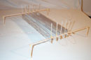
Having now acknowledged experimental limitations, I do believe the results showed that when the corona wire was set at about 3.5cm, with a gap between capacitors at around 4cm to 5cm, this maintained (in my opinion) a fair balance between the KVs required to achieve lift, and mAmps drawn. No doubt this rather narrow scale of high voltage power restricted results, yet within the limits of my Glassman EH Series HV Power Supply, it preformed admirably.
As for example, with emitter wire height set at 4.5cm, and capacitor plates spaced 2cm apart, this required >30KVs, which was way too much for my puny power supply. At the other extreme of configurations possible with this adjustable Tinker Toy Lifter, with the wire was place at 2cm above the foil, and plates space at more than 5cm apart, this caused a significant jump in mAmps, accompanied by almost immediate arcing, which automatically shuts down the sensitive Glassman Power Supply. So as one might expect, when configured somewhere in the middle of these two extremes, everything works smoothly and as it should, with a proper KV/mAmp balance being maintained.
I will leave it to more disciplined minds to explain these experimental results in technical mathematical terms, as such details are just way beyond my simple mind to comprehend. Perhaps I can find time to provide additional results from future experiments, once I’ve completed a few more test runs. (With nearly 200 recorded test flights on the Tinker Toy Lifter to date… this has proven to be a most durable design)
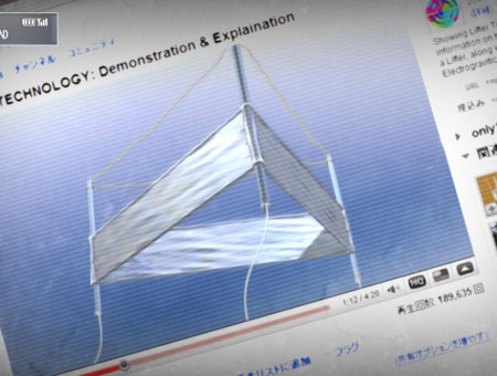
This short video is an attempt to visualize the electrogravitic field comprised of charged ions, and see how far they extended out from the Lifter. Through this crudely executed methodology, imagined I might better perceive was going on if I dangled small, extremely light foam objects in proximity to the surrounding field, then carefully observed any reactions. Certainly not a particularly rigorous criteria for experimental science, but an interesting video just the same.
Another lazy afternoon… And another chance to break out Lifter equipment for a quick visualization experiment. In this test, I attempt to better demonstrate the effects of ion wind on incense smoke as it swirls around within the known Lifter electrokinetic field. To be clear, the Lifter community as a whole never suggested ion wind wasn’t the primary propulsive force at work here, only that T.T. Browns own vacuum tests, hung upon fine balances, indicated there is genuinely some additional motivating principle involved with these charged asymmetrical capacitors.
Other Alt - Think Related Topics...
Replication of T.T. Brown’s Electrokinetic Apparatus
Converting Electrical Potential into Electrogravitic Propulsion
Lifter Project – Experimental Inquiries into Electrogravity
Probing Intangible Limits of Electrogravitic Knowledge
Lifter Project – Assorted Electrogravitic Examples
Purpose Built Collection of Lifter Designs
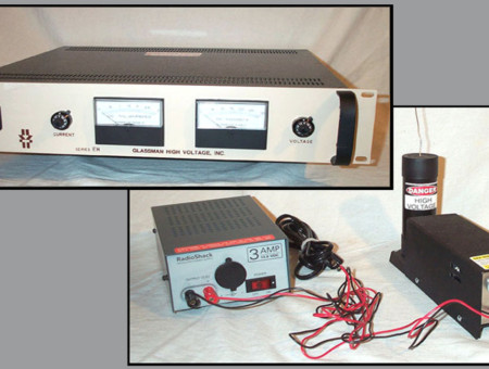
The Lifter Project – High Voltage Power Supplies
Glassman EH Series & Info-Unlimited GRA-30
Electrogravitics – History of an Unorthodox Theory
Electrokinetic-Ion Propulsion or Genuine Gravity Modification?

Nikola Tesla – Possibilities Of Electrostatic Generators
Article from Scientific America - March 1934
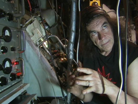
The John Hutchison Effect
Crystal Batteries, Zero Point Energy and Gravity Modification

Richard Feynman – Early Talk On Nanotechnology
"There's Plenty Of Room At The Bottom"
Jean-Louis Naudin – The Quest For Overunity
Propellantless Propulsion, Cold Fusion, and Magnetic Motors
Taken For A Ride – Corporate Conspiracy Against Public Transit
The Great American Public Transit Swindle

The Trap: What Happened to Our Dream of Freedom
Three Part Documentary Series by Adam Curtis

Electric Universe – Plasma Cosmological Theory
Effects Of Electromagnetism upon Large Scale Cosmic Structures
Thorium – Safer and Greener Nuclear Energy
Recent Developments in Liquid-Fluoride Thorium Salt Reactors


Chapter 10 – Capture Of Energy By Resonance
The Sea Of Energy In Which The Earth Floats
Chapter 08 – Reactions By Electron Excitation
The Sea Of Energy In Which The Earth Floats
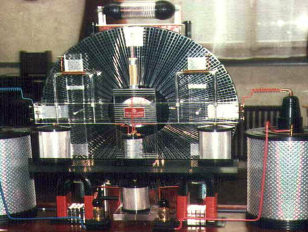
Testatika – Electrostatic Energy Generator
Swiss Methernithans Electrostatic Amplifier and Energy Converter

Aquatic Ape Hypothesis – Elaine Morgan
Controversial Physical Anthropology Alternative Evolutionary Interpretation