Thomas Townsend Brown - Electrokinetic Apparatus
Replication Of Original Patent #2949550, approved Aug 16th 1960
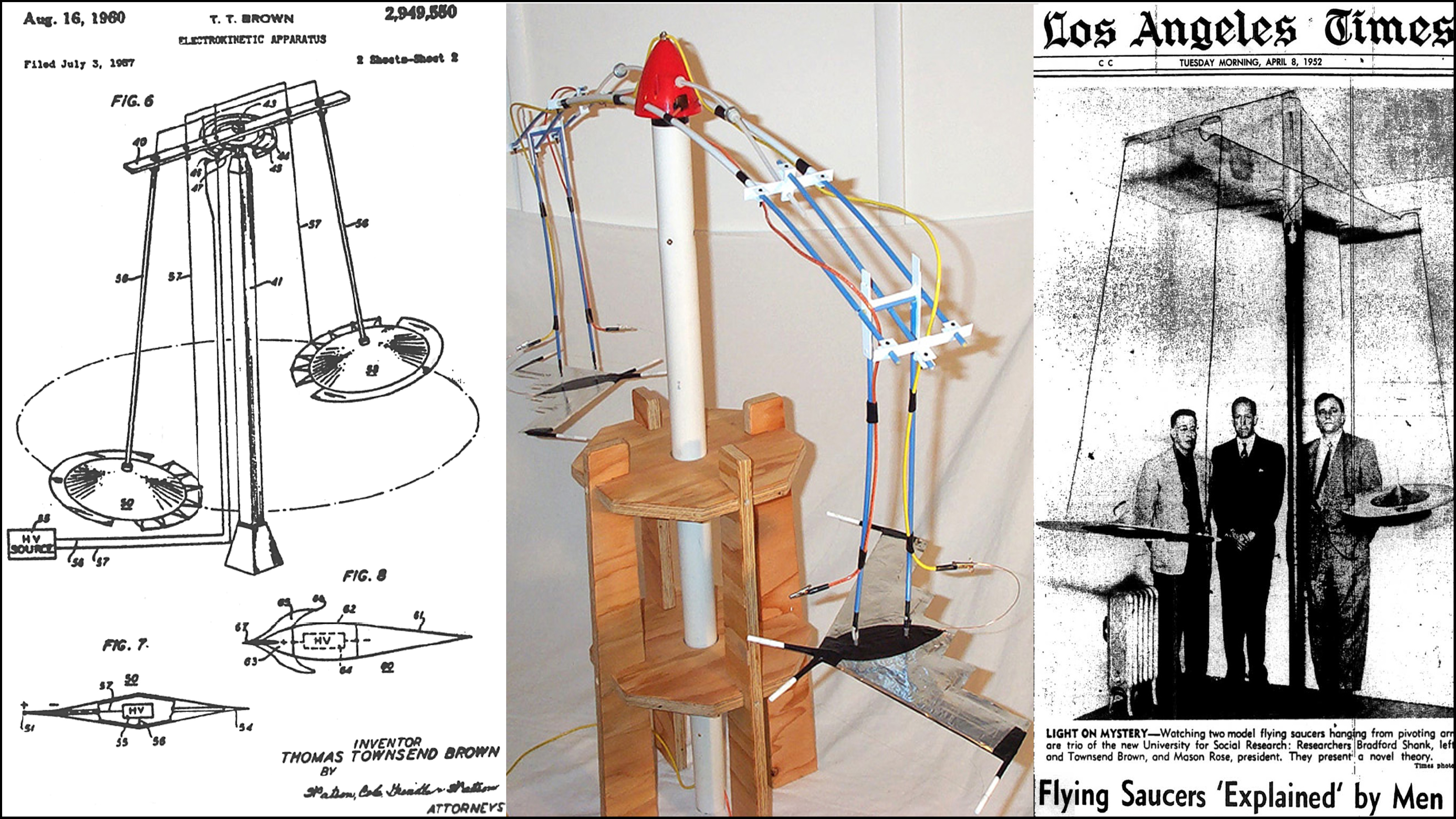
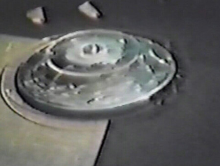
Contained in his original 1960 Patent #2949550, for his Electrokinetic Apparatus, T. Townsend Brown describes his invention as a means for converting the energy created by electrical potential directly into mechanical force, and thus causing relative motion between a charged structure and it’s surrounding medium. The primary objective of this invention was transforming electrical potential directly to usable kinetic motive force. Fundamentally, the device provides an extremely novel way to convert electrostatic potential directly into a kinetic energy, propelling a vehicle motivated solely by electrostatic energy, without using even a single moving part.
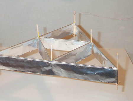
 The key feature producing this relative motion between structure and surrounding medium is a pair of appropriately designed asymmetrical capacitors, each held apart in relative positions to the another, immersed in some dielectric medium (in this example: air) and then oppositely charged to well over 20kv.
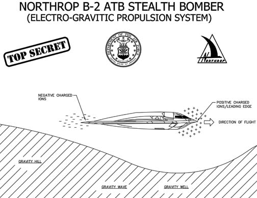
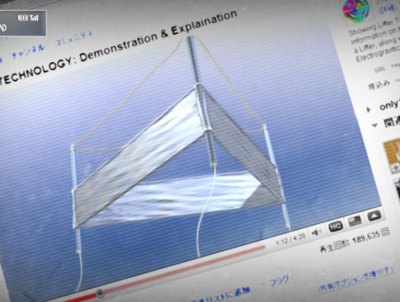
The principle upon which these vehicles operate does appear peculiar, since Brown’s original saucers had no visible propellers, nor jet engines, in fact no moving parts at all. The basic theory is surrounding the capacitors is a modified gravity field, analogous to being placed at the incline on the top of a hill. Another example would be this behaves much like a surfboard riding on a wave…. The electro-gravitational field creates its own portable “hill” in which an intense focused distortion of the local gravity field occurs, allowing this “hill” to essentially push objects forward in a chosen direction. It is assumed occupants of one of Brown’s saucers would also feel no inertial stress, regardless of how sharp the turn or how great the acceleration. This could be attributed to the vehicle and it’s occupants responding equally as one to the wave distortion in this localized gravitational field.
Since his own research years ago, Brown’s developments have progressed further to become an entirely new field of scientific investigation, which today is collectively referred to as electrogravtics. As much remains uncertain regarding the mechanisms of gravity, I continue to maintain an open mind to such technology. Perhaps it really is possible to directly locally modify a contained gravity field through the use of only a separated high-voltage electrical charge.
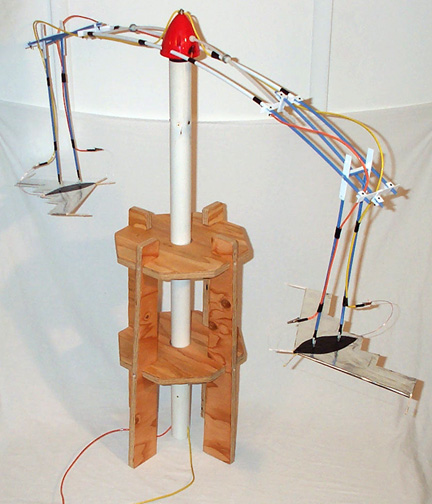
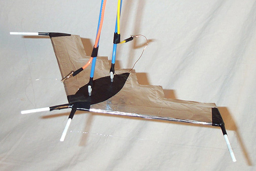
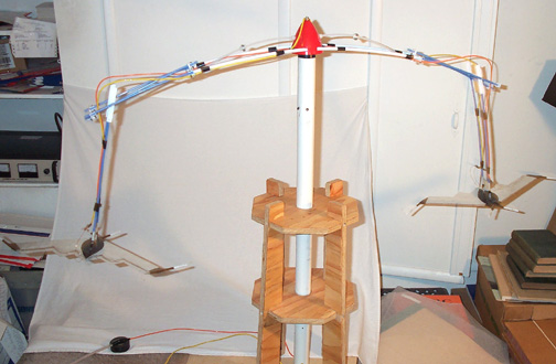
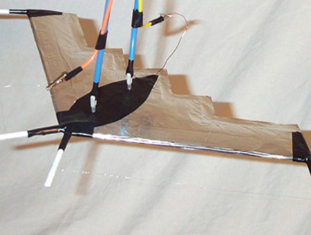
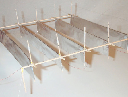
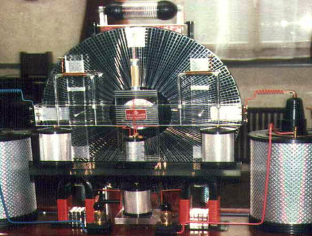
As illustrated in the following series of photographs, while Brown used flying saucers, my own replication employs a pair of B-2B style flying wings. Each foil covered wing has a 17 inch span, is 6 inches in length nose to tail, with necessary 7cm forward protruding emitter wire supports. The fabricated Electrokinetic Apparatus gantry rises up a total of 38 inches in height, while the armature span stretches out 44 inches across from end to end. Dangling from side are two 14 inch long swinging attachment points, from which these charged lifter wings receive their required +20kv DC current. The connections between wing and trapeze are flexible, and very securely attached, as I really don’t want some whirling, high-voltage flying object suddenly coming loose during operation, now would I?
 These experiments were ordinarily conducted using an older and rather fragile Information Unlimited GRA-30 25kv@1ma DC Power Supply, primarily due to it’s lack of self protecting safety features. Essentially, the Info Unlimited unit will not abruptly shut off automatically, unlike the more protective design of the Glassman EH Series DC Power Unit, when high voltage shorts cause beautiful blue sparks to fly! During testing, even brief electrical arcing events would shut down my more refined Glassman power supply immediately. And, as we know from experience, sparks do tend to be a fairly regular event, in fact startlingly frequent even in the most carefully constructed Lifters.
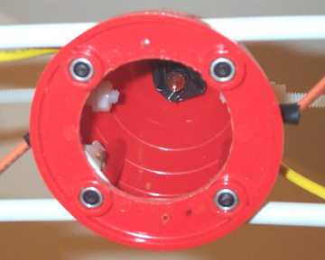
 So there I was, inspecting a freshly constructed pair of modified B-2B wings, potential leak areas tightly sealed within electrical tape and plastic tubes, ready to charge up for yet another electrogravitic experimental test flight. With the wings securely attached to the armature, forward emitter wires carefully set to the full 7cm gap, everything triple checked, turned on the high voltage power, and GERRZAPP! Tremendous crack of explosive arcing flashes unexpectedly inside the red spinner cap, while the rotor pathetically sits motionless. For a moment arc light brightly illuminated the entire top of the supporting column, then I immediately cut power… and thought about what happened.
The error in my design quickly became obvious: With the emitter wire gap set at the full 7cm, this distance is actually greater than the narrow space separating the internal Positive from Negative electrical contacts, as they were integrated within the red plastic spinner. Of course, I was soon able to restart these Lifters using a more conservative >3.5cm gap for the emitter wire. In hindsight, with all those assorted leaks filled with plastic at the lifter end, all the excess electrical current simply jumped crossed the shortest path to complete the circuit, which frustratingly happened to be the far shorter path than was needed to charge up this pair of B-2B Lifters for their circular flight.
So back to the old tool box, I dig around through building supplies, looking to bodge together a quick solution to this unanticipated problem. Subsequent efforts focused upon more thoroughly electrically insulating the supporting copper rod within the base, while simultaneously insulating the corresponding pointed copper rod fitted up inside the top of the spinner cap. Every surface of exposed conducting metal was filled in with either thick insulating foam, or multiple layers of electrical tape. The assumption (since I can’t actually see what’s going on within the spinner) is the remaining exposed electrical air gap between the top and bottom sections must have been reduced to somewhere around <1cm. With fingers crossed for luck, I went on to reassemble various retrofitted parts, and proceeded to once again power up the experiment…
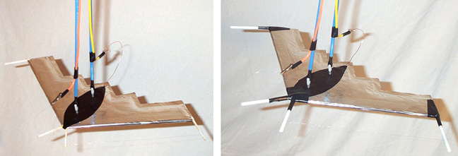
 Getting back to how this replication was actually accomplished, there are some interested design details seen in these images. For example, there is the inner structure of the central spinner, as well as numerous small parts comprising the wide span of the flexible main armature. Among the more essential pieces incorporated in this design was the placement of two threaded nylon rods, stretching out down the arms, each holding a group of steel washers between nylon nuts. By using this simple mechanism, I could quickly make tiny adjustments to the delicate balance of the armature, allowing for maximum rotational efficiency once the wings are attached securely, and wired up for power at each end.
Perhaps the most entertaining puzzle to sort out was the construction of these trapeze like extensions, with attachment points and power connections hanging down to where the lifter wings are actually hung. Prior to installing the colored wire, these swinging attachment points swung quite freely, but after rigging them with 16 gauge braided copper wire, this movement stiffened up significantly, while allowing the wings to pivot outward upon reaching higher rotational speeds. To be honest, everything seen here was assembled using “off the shelf” hobby shop parts, fabricated with dabs of glue, and simple hand tools. Yet many small parts were also heavily modified, or otherwise adapted for use in this project, sometimes in ways for which they were clearly not intended. For me personally, it was gratifying when all these assorted bits and pieces finally came together as a whole, and functioned as expected… Well worth all those earlier failed experiments you will never see or hear about.
 These fabulous B-2B Spirit Lifters have been safely tested with a maximum >5cm emitter wire gap, powered up to >26KVs @ 0.3ma, and in this configuration, only exhibiting infrequent, minimal arcing between wing and emitter wire. Thus, after much patient fine tuning, have completed several measured speed run tests. Observing an average 37rpm, making a sustained velocity for these B-2B wings calculated to be 6.384mph. While not exactly “earth escape velocity” please consider the following: The full size USAF B-2B Bomber has a 172 foot wingspan, which would equal 123.5 of my tiny Lifters. That would establish a scale speed of approximately 788mph for this humble pair of high voltage toys! Now we’re talking some serious Electrogravitic propulsion progress being make… Onward and upward to that next high flying experiment!
experimental experience necessitates minor modifications to the
B-2B Spirit Lifter
After only a few minutes of operation at >20KVs, it became apparent fairly quickly there was a huge amount of electrical leakage in the original design. Most of the arcing was focused along the protruding balsa supports for the emitter wire, especially around the pointed nose of each wing. First I trimmed the aluminum foil back around corners, then reinforced the forward balsa supports with 1cm plastic tubing, extending each emitter wire out from 4cm, to a full 7cm on each wing. (As earlier research suggested this would offer lots of potential thrust!) Everything once again tightly sealed with a generous amount of black electrical tape, with the bases of the plastic tubes firmly secured to the wings. These minor modifications proved especially satisfying, as such structural changes would be impossible to utilize in most typical lifter construction, if I actually still wanted it to fly… Since it was unnecessary for these B-2B style wings to generate enough Electrogravitic thrust to achieve independent flight, those previously unsuitable heavy materials and weighty methods then became available for more serious consideration.
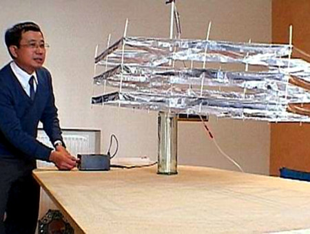
In fact, a few bright minded individuals over at MIT have figured out how to build a small high voltage battery power supply that is light enough to ride inside an actual model airplane, which then successfully achieved the first free flight of a ion drive aircraft! Truly an amazing accomplishment!
B-2B Lifters on Electrokinetic Apparatus
25kv @ 0.3ma, 5cm wire gap, rotating at approx 35+rpms
Other Alt Think Related Topics...
Replication of T.T. Brown’s Electrokinetic Apparatus
Converting Electrical Potential into Electrogravitic Propulsion
Lifter Project – Experimental Inquiries into Electrogravity
Probing Intangible Limits of Electrogravitic Knowledge
Lifter Project – Assorted Electrogravitic Examples
Purpose Built Collection of Lifter Designs
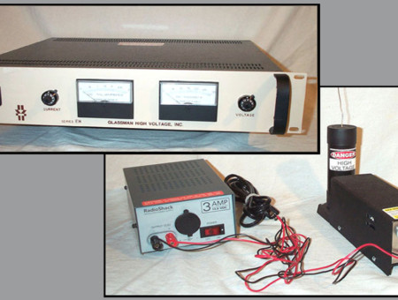
The Lifter Project – High Voltage Power Supplies
Glassman EH Series & Info-Unlimited GRA-30
Electrogravitics – History of an Unorthodox Theory
Electrokinetic-Ion Propulsion or Genuine Gravity Modification?

Nikola Tesla – Possibilities Of Electrostatic Generators
Article from Scientific America - March 1934
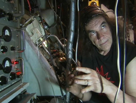
The John Hutchison Effect
Crystal Batteries, Zero Point Energy and Gravity Modification

Richard Feynman – Early Talk On Nanotechnology
"There's Plenty Of Room At The Bottom"
Jean-Louis Naudin – The Quest For Overunity
Propellantless Propulsion, Cold Fusion, and Magnetic Motors
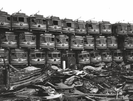
Taken For A Ride – Corporate Conspiracy Against Public Transit
The Great American Public Transit Swindle

The Trap: What Happened to Our Dream of Freedom
Three Part Documentary Series by Adam Curtis

Electric Universe – Plasma Cosmological Theory
Effects Of Electromagnetism upon Large Scale Cosmic Structures

Thorium – Safer and Greener Nuclear Energy
Recent Developments in Liquid-Fluoride Thorium Salt Reactors


Chapter 10 – Capture Of Energy By Resonance
The Sea Of Energy In Which The Earth Floats
Chapter 08 – Reactions By Electron Excitation
The Sea Of Energy In Which The Earth Floats
Testatika – Electrostatic Energy Generator
Swiss Methernithans Electrostatic Amplifier and Energy Converter

Aquatic Ape Hypothesis – Elaine Morgan
Controversial Physical Anthropology Alternative Evolutionary Interpretation